
UMC – Rapid Calculation of the Radiofrequency Field Pattern in MRI #SWI2007
Introduction
The physical principle of MRI is based upon the application of a strong static magnetic field to the patient. This field forces the magnetic spin moment of hydrogen nuclei in the patients to precess around the external field with a particular frequency which scales proportionally with the magnetic field strength. Central in the imaging process is the application of radio waves by a so-called transmit coil. When this coil generates a pulsed radio wave with a frequency exactly equal to the precession frequency, a resonant energy transfer takes place. This shifts the precessing nuclei to a higher energy level. After the radio pulse, the nuclei return to their equilibrium by emitting a small radio wave of their own. This signal is recorded by external coils and processed to create an image.
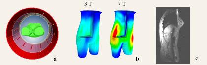
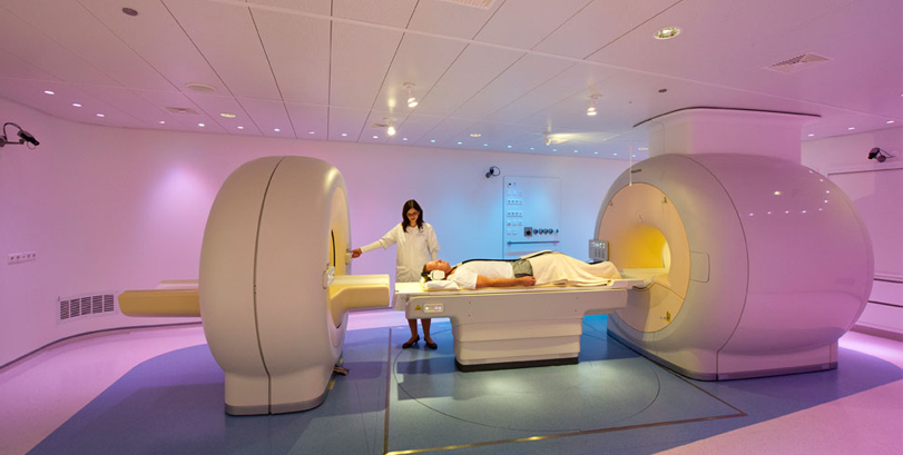
Figure 1: a:) In an MR scanner, the patient is surrounded by antennas and an RF shield which serves to shield off external RF disturbances. b:) The inhomogeneity of the RF excitation field becomes a severe problem at 7 Tesla, also illustrated by a sagittal MR image of the human abdomen (c) showing a central line with low signal due to a null in the excitation field.
Topic of investigation
The radio waves are generated by a so-called transmit coil which consists of a series of parallel copper rod-antennas carrying electric currents with a fixed mutual phase and amplitude. See Figure 1a. The interference of the waves and their dielectric interaction with the human body results in a certain spatial excitation pattern. This field is the object of this investigation. Ideally, this radio-excitation of the hydrogen nuclei should be constant throughout the patient to obtain an image contrast that is only due to anatomical differences. However, the application of radio waves at high magnetic field strengths poses some problems. At 7 Tesla the required frequency of the radio waves is 300 MHz. At this frequency, the wavelength is smaller than the transverse dimensions of the patient, leading to a highly inhomogeneous excitation pattern. See Figure 1b. As a result, images of the abdomen and pelvis at higher field strength suffer from image artifacts as is demonstrated in Figure 1c.
One possible method to minimize these problems is to abandon the fixed amplitude and phase relation of the currents in the antennas. By modulating the phase and amplitude of the currents in the antenna individually, the interference of antenna fields will be altered in the patient. This creates a way to steer and optimize field distribution. We have tested this by performing numerical electromagnetic simulations using the Finite Difference Time Domain Technique. See Figure 2a. We discovered that the radiofrequency field pattern is not highly patient-specific but is mainly affected by the elliptical shape of the abdomen and pelvis, as is demonstrated in Figure 2b. Furthermore, in the abdomen and the pelvis, the problem becomes almost a 2D problem.
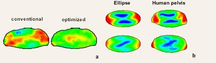
Figure 2. a:) By exploiting phase/amplitude modulation of the individual antennas the interference of the fields can be optimized to obtain a better spatially equal excitation. b:) The RF magnetic (top) and electric (bottom) field of an ellipse (left column) and the human pelvis (right column) are very similar.
Prompted by these observations, we believe that an on-the-fly optimization procedure should be possible, i.e. after the patient has been positioned in the MR scanner the optimal phase/amplitude settings are being determined. Such a concept would require a rapid computation of the radiofrequency field distribution in the patient based on a simple elliptical model of the patient’s anatomy. To make this concept practically feasible, this process should be performed in a matter of 1 or 2 minutes. Numerical techniques such as the Finite Difference Time Domain technique are much too slow for this purpose, which leaves an analytical model as the most feasible option. We also expect an additional benefit from such an analytical model due to the better physical insight it can provide about certain aspects such as the ultimate limit of the homogeneity and the occurrence of resonant modes in the circular cavity at specific frequencies.
Model definition
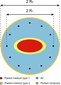 The setup consists of a circular copper shield, which can be assumed to be a perfect conductor. In the center of the shield, an ellipse is placed with an arbitrary eccentricity. The ellipse consists of two confocal elliptical layers, each with unique, homogeneous dielectric properties. The patient is surrounded by N evenly distributed antennas, which can be thought up as line sources, carrying an AC electric current with frequency F and flowing perpendicular to the plane. Each antenna generates an AC electric and magnetic field. The analytical solution for this problem should be able to calculate the complex electric and magnetic field of an individual antenna as a function of the phase and amplitude of the current carried by the antenna. The total field pattern is calculated from a superposition of all the antenna fields according to the phase and amplitude settings of the antennas.